Coupling Adjustment and Correct Alignment in Centrifugal Pumps
KSB and other manufacturers usually deliver the pump mounted on a base and with the electric motor connected via a coupling. However, vibrations occurring during transportation and installation of the pump in its final location disrupt the alignment of these equipment. Therefore, after the assembly and concrete of the pump is completed in accordance with the specified conditions, the coupling adjustment must be made again. Additionally, realignment is required whenever the pump or motor is moved or relocated for maintenance or any other reason.
What do we mean by 'alignment'? In coupling pumps, the power received from the engine is transferred to the pump shaft through a coupling. Under ideal conditions, these two shafts (pump shaft and motor shaft) should be exactly parallel and have the same centerline. Flexible couplings can tolerate minor alignment errors, but for ideal, trouble-free operation, it is necessary to ensure that these two shafts are aligned within the tolerances specified by their manufacturers.
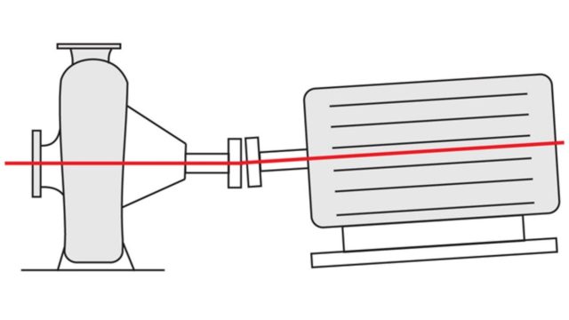
There are two types of misalignment that can cause operating problems. The first of these, Angular Misalignment, occurs when the center lines of the motor shaft and the pump shaft are at an angle to each other, as shown below.

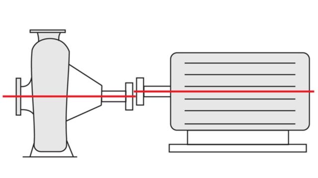
Parallel misalignment is the situation where the pump and motor shaft are parallel, but the center lines are in different positions relative to each other, either vertically or horizontally.

Generally, both types of misalignment are observed together in pumps with misalignment or misalignment of the coupling.
Measuring Alignment The first step in properly aligning motors and pumps is measuring the degree of misalignment.
Açısal hizalamalar için basit bir uygulama aşağıdaki gibidir:
- With the motor and pump shaft flanges close together but disconnected, mark a point on each shaft and then measure the distance between them with a feeler or taper gauge.
- Rotate both shafts approximately 90 degrees, keeping the marks close together. Measure the separation distance again. Repeat for 180 and 270 degrees.
- If the measured separation remains the same as the shafts are rotated, they can be assumed to be parallel. However, differences in measured flange separation indicate that the shafts are not perfectly aligned.
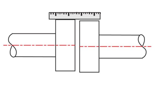
A similar procedure can be used to measure parallel alignment. Here, a straight gauge is placed on one of the flanges and the distance to the other flange is measured (as below).

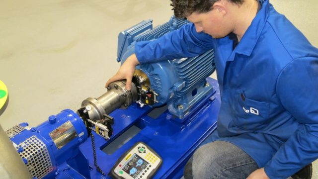
Laser measuring devices are often used for alignment between motor and pump shafts. Laser alignment devices provide higher levels of accuracy.

Checking alignment with laser measuring equipment
Correcting Misalignment
Since the pumps are usually connected to the line, it is easier to move the motor. Minor adjustments to engine position in the horizontal plane are usually accomplished by loosening the engine anchor bolts, shifting the engine sideways, and then retightening the bolts. Vertical adjustments are usually made by adjusting leveling screws or adding or removing shims under the engine mounts. Care should be taken in shim selection. A few relatively thick shims are preferable to a set of thin shims. Because thicker shims generally provide stiffer and safer supports for the engine. Naturally, when the pump or motor is repositioned, the alignment needs to be rechecked.
Foot Problems
Bent, damaged or poorly installed pedestals, improperly selected shims or loose anchor bolts all cause a condition known as soft or spongy feet. When this occurs, it will be very difficult or even impossible to properly align rotating machines. Even if everything seems fine when the pump is not running, operating loads, including motor torque and thermal stresses, can throw things off once the pump is running. Modern laser coupling alignment devices can help detect foot problems by measuring small changes in the position of the pump and motor.


